Overview
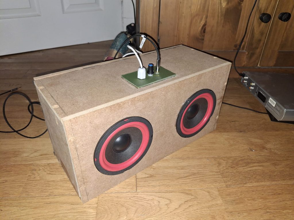
TALK ABOUT WHAT WAS ACTUALLY BUILT, WHAT WAS INVOLVED AND A BRIEF TOUCH ON THE END RESULT
In this project, I designed and built my own 30W stereo speaker. Its quite versatile, as it can be used for listening to music as well as for watching music / playing video games. The speaker’s driver produces a very high maximum volume, making immersive horror games particularly enjoyable. The speaker drivers were designed to be simple and efficient, with a primary focus on producing a clean signal with minimal distortion as well as having stable thermal characteristics for prolonged listening sessions. The speaker is powered by USB-C power delivery, which means that it can run off of a compatible power bank for outdoor / portable use-cases.
Background
THIS PART IS SUPPOSED TO BUILD A NARRATIVE ON WHY I BUILT THIS PROJECT
Although I am a Software Engineer by formal education, I have always been interested in electronics. In my first two years of University, I took as many elective electronics courses as I could fit in my schedule. In fact, I was taking so many electronics courses on the side that at one point, my adviser of studies informed me that I could switch to a degree in Electronics and Software Engineering, as I met all of the course requirements. I ended up sticking with Software Engineering however, as the degree programme allowed for me to take a full year in industry, unlike the ESE degree. Anyways, this passion for electronics always stuck with me, I loved learning the theory about electronic components, and my elective courses took me through the basics of both analogue and digital electronics. I learned about many components, although one always stood out to me as quite a spectacular thing – the operation amplifier. Opamps are one of the most widely used integrated circuits in modern electronics, they can be used for audio, analogue signal processing, handling digital signals and more. They are truly remarkably versatile and complex components.
Infatuated with the prospect of building my own audio systems, I immediately attempted to build my own speaker. It used a small quarter-watt speaker and a couple of TL072 opamps. I had a lot of fun building this speaker, and I learned a lot about opamps, particularly about real-world physical constraints involved in using them, such as issues with single-supplies being unable to output negative parts of input waves without biasing and practical current output limits of real opamp ICs, which are typically around 50mA. This makes driving a low-impedance speaker with more than a fraction of a watt difficult without further components. I ended up switching to an LM386, which wasn’t an opamp but rather a small power amplfiier IC which could drive my speaker.
Fast forward about 3 years and I finally decided to revisit the project of building my own speaker. I remembered the underwhelming volume and low audio quality of my first speaker, and believing that I was much more knowledgable about electronics now, I started this ambitious project!
I already had a stockpile of various components at home, from resistors and capacitors to dual opamp packages like the TL072. So all I needed to buy in order to start designing my driver were the actual speakers and some output stage transistors. I purchased two cheap, but fairly sensitive 25W 4Ohm speakers with a 5inch diameter, setting myself up for a significantly bigger speaker!
What originally sparked this, or kicked me off to actually start building it, was the terrible sound quality of our old TV’s builtin speakers, which reflected and ‘rumbled’ for certain ‘spooky’ low frequency ambient noises. I thought, if this speaker is good enough, we could use it as a sound bar, and i must say it is quite satisfying to build something that actually works, and works well at that and can actually be used for the intended purpose!
Electrical Design
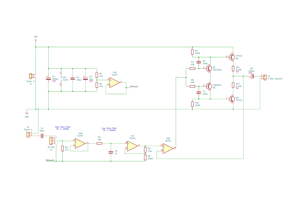
Single Supply Design
My driver works with a single supply. This means that a standard DC voltage supply can power the circuit, as opposed to some circuits which require a split-suply with positive and negative rails.
When first learning to use Opamps and work with audio signals, it is common to design split-supply circuits, as this greatly simplifies the circuit design. This is because audio signals are AC signals which swing below 0v – having a split supply allows Opamps to handle audio signals as inputs directly. However, when designing a real circuit that is to be used practically, using a split supply requires either a centre-tapped transformer from a mains supply or powering the circuit using batteries: i.e. using two 9V batteries in series to provide a +/- 9v split supply.
Since I wanted the speaker to remain versatile so that it can be used in a portable fashion (i.e. with a power bank) and at home using a mains supply, I decided to stick with a single supply design. However, this requried some extra design tricks in order to be able to work with the audio signal.
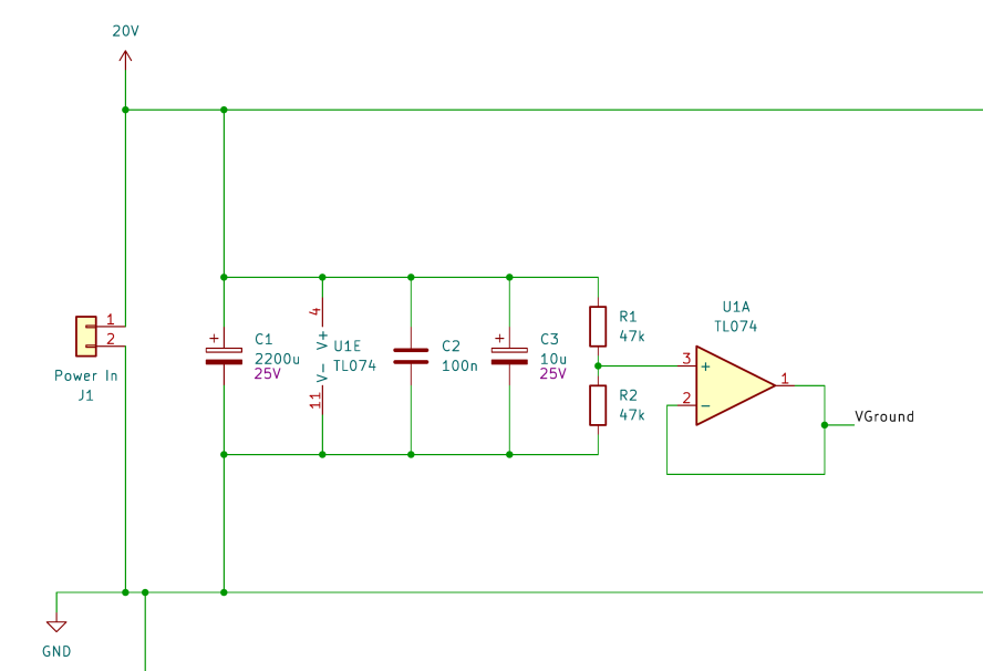
Firstly, the opamp’s input pins could not be directly connected to the negative-going AC audio signal. Before the opamps can see the audio signal, we must apply a DC bias – a fixed offset voltage which places the AC signal within the rails of the single supply. This can be done with a simple resistor divider network to make a reference voltage, I use half of the positive voltage rail which is 10v.
Now that the signal is biased, it can go into the operational amplifier inputs. However, all circuits which would usually be connected to ground now need to be connected to the bias voltage – the virtual ground. This goes for RC filters as well as Opamp feedback networks. Since the DC bias is connected to various different networks, I wanted to ensure that the DC bias voltage remains stable and so I put it through a voltage-follower buffer (yet another use of Opamps!) before feeding it to other areas of the preamplification stage.
Preamplification
Before sending the signal to the speaker, it needs to be processed in several ways such as setting a fixed DC bias, handling volume control, attenuating unwanted frequencies and amplifying the signal’s voltage. This is done in the preamplification stage of the circuit, which is composed of multiple processing stages separated by Opamps.
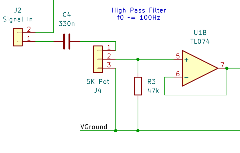
This first stage of the preamp simultaneously does 3 things. First, it blocks any DC bias that the input signal may have been riding on and biases it with the mid-supply virtual ground through a 47k resistor. Second, it acts as a volume control using a 5k potentiometer dividing the input signal at the opamp input. Third, the 5k potentiometer and the 330nF capacitor work as an RC high-pass filter with a cut-off frequency of approximately 100Hz. This filter blocks very low frequency components outside of the speaker’s range.
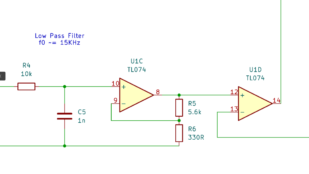
The second stage of the preamp serves two purposes. First, an RC low-pass filter blocks high-frequency components with a cut-off frequency of approximately 15KHz. A 20KHz cut-off would have been better, but I settled with 15KHz so that I could use components I already had. Second, the opamp amplifies the voltage level with a gain of 18. This sets the sensitivity of the driver to maximum volume at 0.4V RMS, which fits well with standard aux voltage level of around 0.5V RMS, leaving some headroom for quieter signals. Finally, the signal is fed into the output stage.
Output Stage
Opamps are a great component. In the preamplification stage of my speaker driver I use them for creating a steady reference voltage, isolating separate circuit stages and amplifying the voltage of the audio signal. However, Opamp chips generally have limited current source/sink capabilities. That means that they aren’t able to drive a load with significant current, this making them unsuitable for driving my 4Ohm speakers.
This is why the driver needs a dedicated output stage which is capable of delivering significant current to the speaker, allowing it to be driven with higher power.
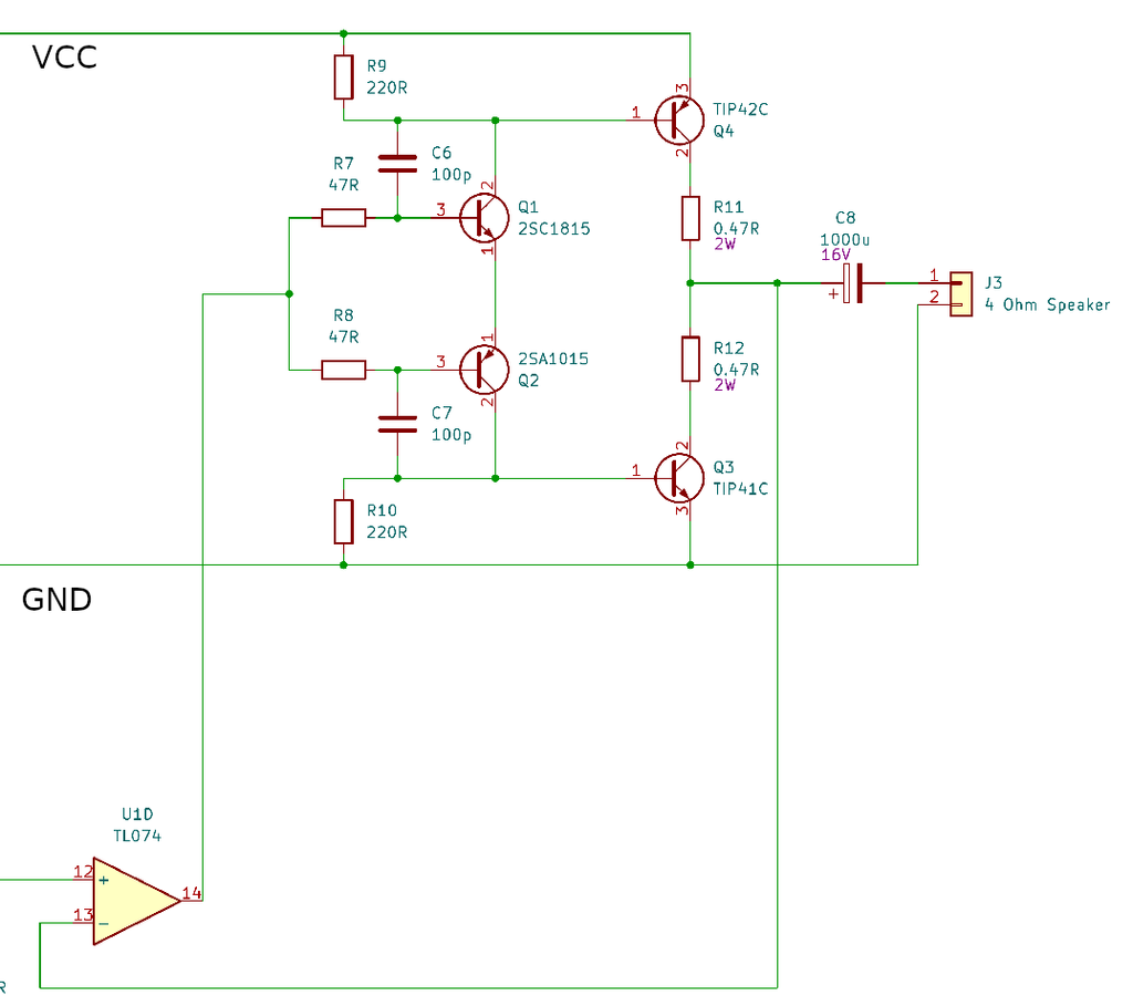
My output stage is designed as a voltage follower – the signal’s voltage level at the output is approximately equal to the voltage at the input. However, it has a current gain such that the output current is much larger than the input current. More specifically, I use a push/pull emitter follower, or a class B amplifier. This circuit works using NPN and PNP transistor pairs, each of which conducts for approximately half of the wave cycle.
Class B amplifiers have two practical issues. Firstly, they are quite inefficient and generate a significant amount of waste heat. This problem can be mitigated with proper heatsinking. The second issue is known as crossover distortion. Since the NPN and PNP transistor pairs require a 0.7V difference to start conducting, for a portion of the audio signal range near the mid-supply (approximately 1.4V) the transistors do not conduct. This effect is called crossover distortion. This can be mitigated by using a class AB design, where proper biasing allows transistors to conduct for slightly more than half of the waveform. This requires careful thermal management and is difficult to implement correctly, as temperature changes can change bias voltages and transistor base-emitter voltage thresholds, leading to thermal runaway. I therefore decided to mitigate crossover distortion through the use of negative feedback with one of the TL074 Opamp channels. The TL074 quickly adjusts the output stage input signal during the 1.4V deadzone to correct for the crossover distortion. It is not perfect, but does a very good job of correcting audible crossover distortion and produces a clean audio output.
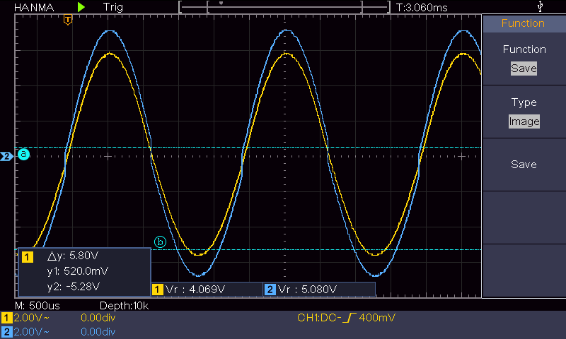
The above osiclloscope trace demonstrates how the opamp corrects for crossover distortion, the yellow output trace is clean with no distortion, whereas the blue trace (input of the push/pull stage) quickly jumps at around 0.7V to -0.7V to correct for the crossover distortion.
The push/pull output stage is built around the TIP41C and TIP42C transistors, which are capable of delivering significant current to a load. However, they have quite a low minimum current gain. This means that a significant base current may be required to drive the speakers, which could stress the TL074 Opamp. I therefore decide to use a Sziklai pair to effectively create a compound NPN-PNP pair of transistors which a much higher effective current gain. This keeps the base current very low, but requires the use of a smaller NPN-PNP pair to form the Sziklai pair. For this I use C1815 and A1015 transistors.
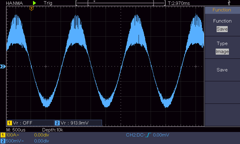
I encountered quite a lot of noise issues while designing the output stage. This led to a few implementation tricks which mitigated these noise effects and led to a cleaner signal coming out of the driver. The first being 47 ohm base stopper resistors and 100pF miller capacitors to reduce high-frequency parasitic oscillations. I added 220 Ohm bypass resistors to provide a discharge path for TIP41/TIP42 bases. Finally, I added 0.47 Ohm emitter resistors at the collectors of the TIP41/TIP42 transistors to help with thermal stability.
Speaker Enclosure
HERE WE TOUCH ON THE SPEAEKR ENCLOSURE