What is an ADS?
“ADS” stands for Autonomous Driving System. It’s a piece of terminology from the Formula Student competition in the UK, which has a special division for self-built autonomous racing cars. If you want to read about my work in Formula Student more generally, click here.
In my last year at the University of Glasgow Racing Team, I was disappointed that we hadn’t made much progress towards building our own autonomous racing platform. While we’d made huge strides in autonomous racing software, we were still relying on an autonomous platform on loan from the Institute of Mechanical Engineers. Complications in our engineering team’s electric vehicle design, plus a lack of cohesion between our software and engineering teams, meant our own in-house autonomous-capable EV never got off the ground.
To remedy this, I decided to embark on quite the ambitious project: build a first-prototype autonomous racing platform myself. It wouldn’t be anywhere near as powerful as the real competition entry, but I wanted to show the team that UGRacing’s own ADS entry wasn’t as out of reach as most people thought, and that the key to getting there was to start small and build up as we go. We didn’t need to design a several-thousand-pound vehicle capable of generating tens of kilowatts. Instead, I proposed we start with something smaller, around 50 watts of power, a total cost of about £250, and a couple hundred hours of work.
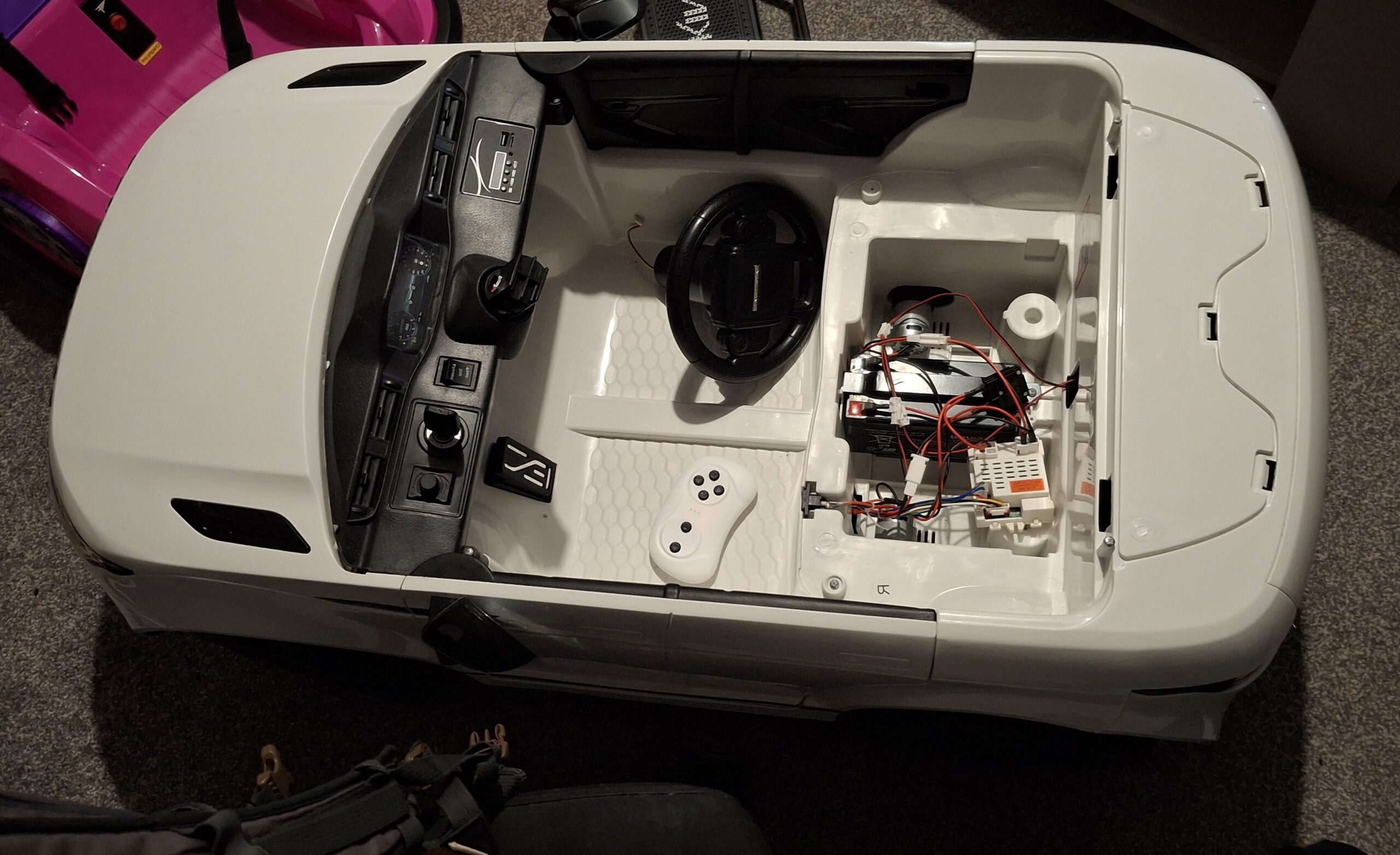
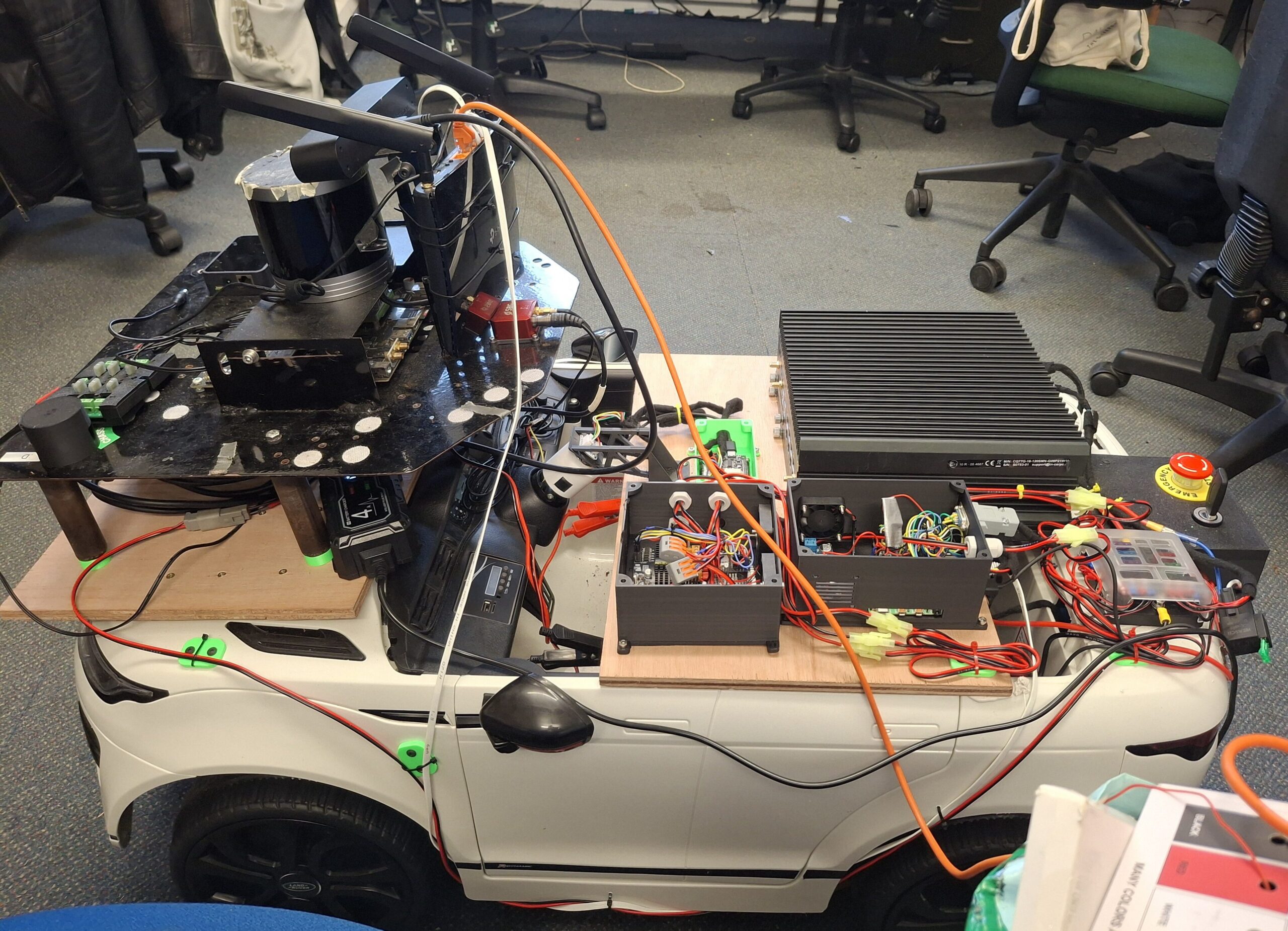
This idea became the MiniADS, pictured above. I bought a used kiddie ride-in electric car for £100 on Gumtree, then modified it to add wheel-speed sensors, steering sensors, motor drivers, compute, an ECU, and appropriate power. What we ended up with was our first ever autonomous racing vehicle prototype, something that could run our software and act as a testing platform through the year, as well as a tangible proof of the ADS concept, one that’ll hopefully inspire incremental improvements and upscaling until we reach the ultimate goal: a full-size ADS we can take to Formula Student competitions around the world.
Electrical Systems
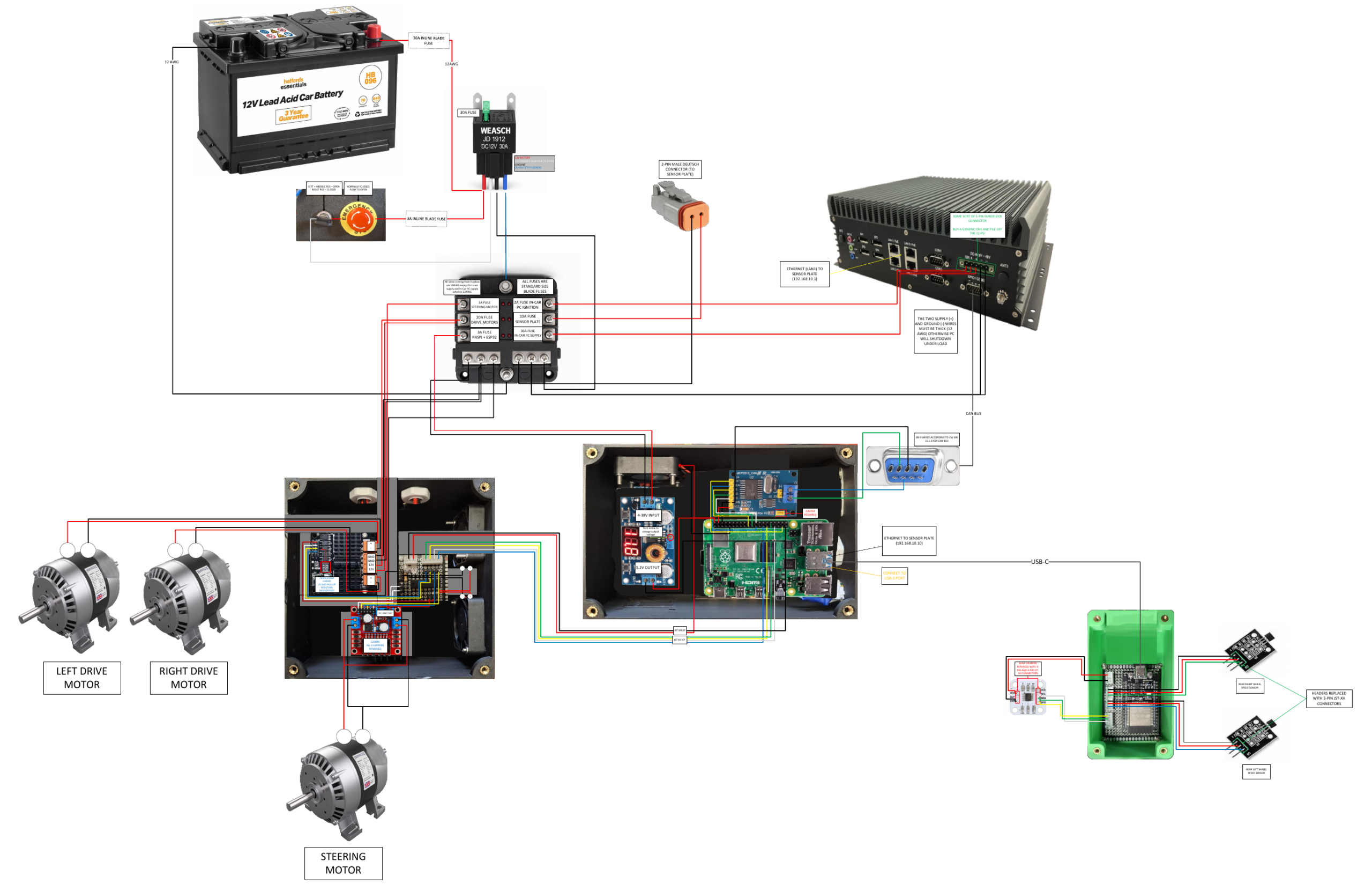
The electrical systems are what I’m most proud of on this project. I’m a Software Engineer by formal discipline, I took some electronics courses in my first two years at university, but most of what I know is self-taught through practice and projects. So designing a full electrical system from scratch for a miniature autonomous vehicle was a difficult but rewarding task. I learned a lot about design considerations like fusing, wire gauge selection, efficiency, cooling, and more.
Main Isolator & Power Distribution
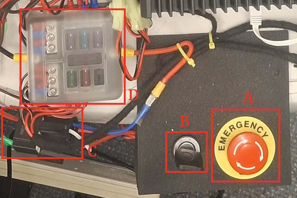
The main isolator controls whether the 12V battery is connected or disconnected from the rest of the circuit. It’s controlled by two physical switches: the emergency stop button (A) and the ignition switch (B). Only a small current flows through these switches, since they’re connected to the main relay (C), which is the actual current path between the battery and the fusebox (D).
The ignition switch was reused from the original vehicle, since it gave us a sensible way to turn the system on or off with a key that could be removed to prevent accidental start-up. The emergency stop button was added as an extra safety measure, so the system could always be shut off quickly in an emergency.
I used a standard blade-compatible automotive fusebox for this project. It could hold up to 6 fuses, and by the end of integration every slot was in use. Not all fuses live in the fusebox, though, 3 inline fuses exist for extra redundancy: a 30A fuse directly at the positive battery terminal to protect against short circuits before the fusebox, a 2A fuse on the isolator line to protect against short circuits in the switch wiring and relay failures, and an additional 30A fuse in the main relay. That last one isn’t strictly necessary, but the relay I bought has a blade fuse slot built in, so I used it.
5V Systems
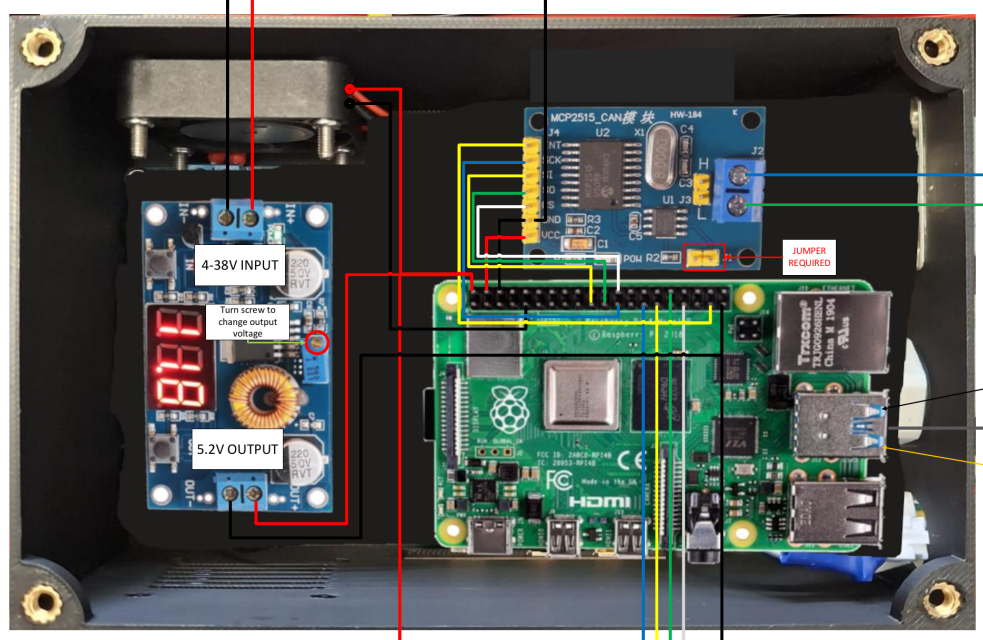
While the drive motors and In-Car PC can run directly off battery voltage, several other components need a 5V supply. These are all powered by an off-the-shelf buck-converter PCB, housed alongside the Raspberry Pi.
The Raspberry Pi acts as the ECU of the vehicle. It talks to the In-Car PC over CAN, which runs the higher-level autonomous driving software and ultimately controls the vehicle’s motion, and is responsible for issuing low-level motor commands as well as processing raw sensor data from the ESP-32.
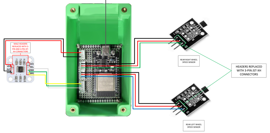
I could have wired the raw sensors straight to the Pi’s GPIO pins, but I wanted to keep a clean separation of concerns: the Pi handles higher-level communication and command in Python, while an ESP-32 (programmed in C++) gathers raw sensor data and sends it over UART. This let the two microcontrollers work at different levels of abstraction, the ESP-32 stays as fast as possible to capture all sensor data, while the Pi reads that data using multithreading. The ESP-32 also keeps a small amount of state to accumulate wheel-speed sensor counts, so if the Pi misses a packet or two, it can still estimate wheel speeds reasonably well.
Motor Controllers
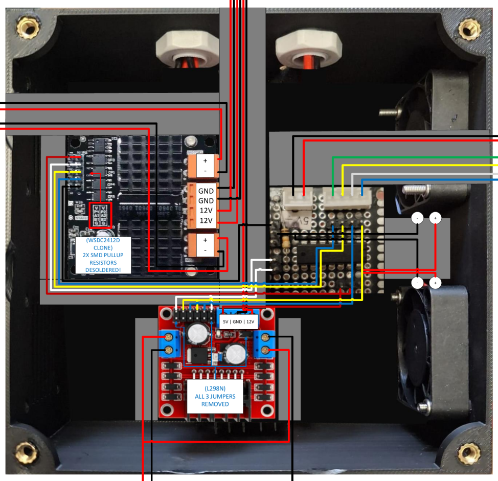
I use two off-the-shelf motor controller PCBs to drive the two drive motors and the front steering motor. Both are powered by the 5V buck converter output but switch 12V to the motors. For the steering motor, I use an L298N-based PCB, a notoriously weak and inefficient motor controller.
In my experience, anything above a few hundred milliamps, even with the output channels paralleled, makes the IC heat up fast, and output power drops off significantly. This is mostly down to the old BJT-based design of the monolithic L298N IC. But since our steering motor only draws around 500mA at peak load, the L298N works fine here.
The drive motors are a different story, each can draw just under 10A to overcome rolling resistance (or when aggressively driving over a cone), which rules out the L298N entirely. Instead, I use an off-the-shelf PCB based on the common WSDC2412D motor controller, rated for 12A continuous draw per channel, much better suited to the drive motors.
Software
A big goal for this project was making the final platform as compatible as possible with the autonomous vehicle we use at Formula Student UK. That meant a large part of the software implementation was about matching the same specifications as the ADS-DV (IMechE’s autonomous racing vehicle).
Beyond that, the software also had to process sensor data and vehicle commands and translate them into low-level motor commands via controllers.
There are three compute platforms on the vehicle:
- In-Car PC, the powerful computer running the same autonomous driving software we use at competition
- ESP-32, a small microcontroller responsible for gathering sensor data and doing minimal preprocessing
- Raspberry Pi 4B, the more capable microcontroller that ties everything together, talking to the In-Car PC and ESP-32, and controlling the motors
ESP-32
The ESP-32 runs a small, simple C++ codebase, kept deliberately minimal so low-level sensor interactions stay separate from the higher-level communication and control handled by the Pi. It connects to the wheel-speed sensors and the magnetic angle sensor over SPI and GPIO.
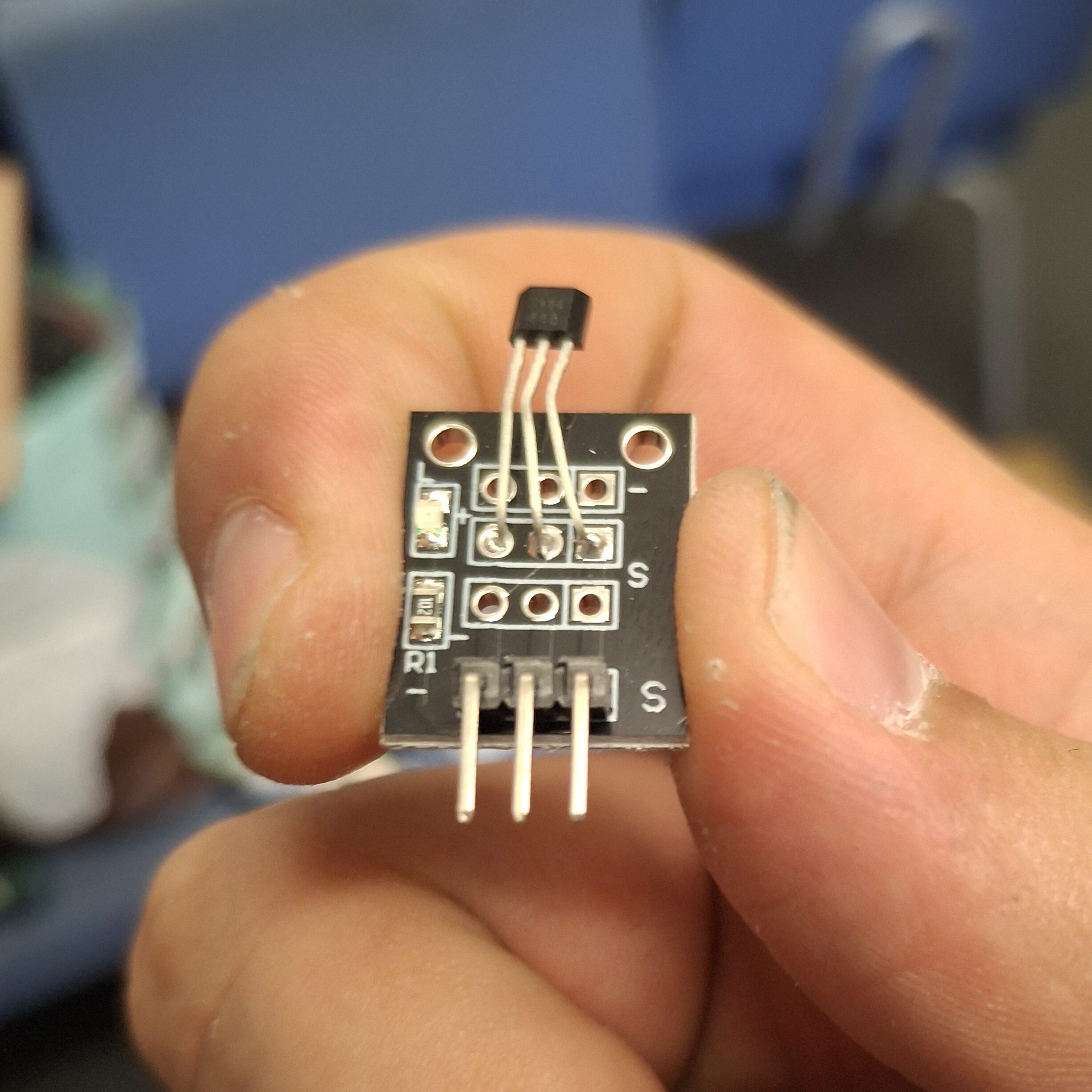
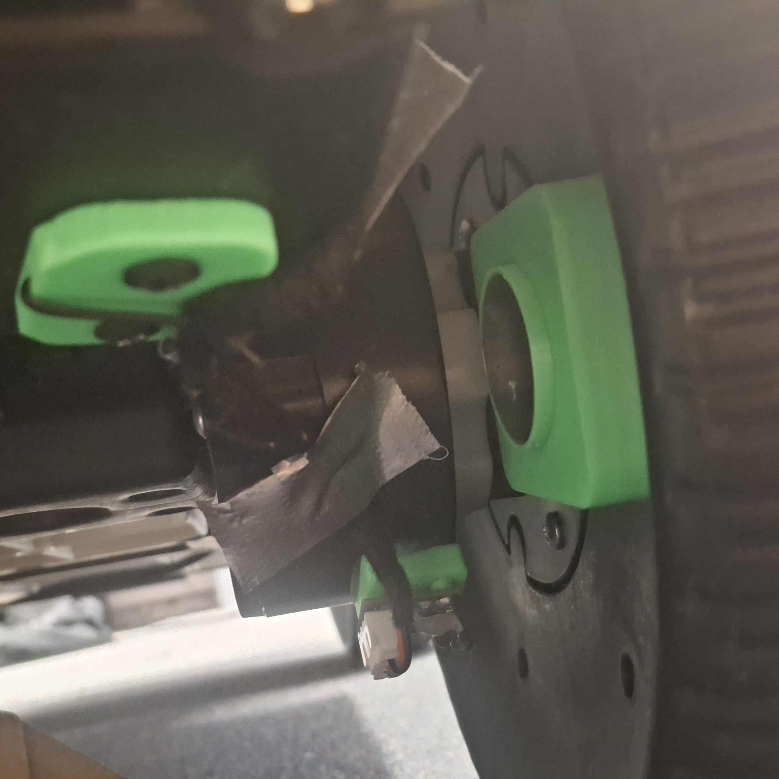
The wheel-speed sensors are basic hall-effect sensors that go HIGH when a magnet is nearby and LOW otherwise. Two of these are mounted at the rear wheel wells, with magnets on the wheels themselves. As the wheels spin, the magnets create pulses, and the timing between them gives us angular velocity, and from that, vehicle speed.
The ESP-32 uses hardware interrupts to catch rising and falling edges from the sensors, does some basic debouncing, and keeps a running pulse count.
The magnetic angle sensor is read over SPI, with the ESP-32 simply reading the current angle as fast as it can.
Every 20ms, the ESP-32 sends the wheel-speed and angle sensor readings to the Raspberry Pi over UART, with an error-check code appended so the Pi can catch the rare cases of data corruption on the line. It’s a simple connection and a simple, robust protocol, which is exactly what you want between two microcontrollers.
Raspberry Pi
The Pi is the vehicle’s main ECU. Its GPIO pins connect to an MCP2515-based CAN transceiver/controller module, giving a direct CAN link to the In-Car PC, alongside the UART link to the ESP-32 over USB.
The Pi’s software is written in Python, chosen to make rapid development possible, widely available libraries, fast iteration, none of the friction of a more heavyweight language like C++. That said, this came with real limitations once we needed concurrency to read sensor data and CAN messages at the same time.
The Pi uses the Python can library alongside cantools, which lets it load the CAN database provided by IMechE, the same message definitions their vehicle’s ECU understands. Using this database keeps everything running on the In-Car PC identical to what we run at competition, over the same CAN interface.
The Pi waits for CAN messages from the In-Car PC. On receiving the first one, it starts the handshake loop defined by the Formula Student spec. It gathers sensor data, wheel speeds, steering angle, and translates it into usable values like RPM per wheel and steering angle in radians, with some preprocessing to filter out bad RPM readings or clip RPM to zero if no pulses have been detected for a while. These readings then go back to the In-Car PC over CAN, using the messages defined in the database.
The Pi also listens for command messages requesting a specific steering angle or wheel speed, then uses PID controllers to drive the motors toward those targets, sending commands over GPIO to the motor driver hardware.
Overall, the Pi’s software is fairly simple, its main job is to run fast enough that it never misses a CAN message from the In-Car PC or a sensor reading from the ESP-32. And since it’s running a PID control loop, the faster it updates, the better the vehicle’s control gets.
That speed requirement does make the code harder to maintain, though: anything that blocks the main thread risks missing sensor readings or CAN messages, which makes misbehaviour during testing painful to diagnose.
To help debug the Pi’s software, I built a simple client-server debugging application. The client side is Python and Tkinter, letting me view sensor readings, CAN messages, and logs remotely over the same network as the Pi. I used ZeroMQ’s Pub/Sub model for fast, socket-based data transmission. This gave us full introspection during testing sessions, and it was especially useful for tracking down issues with the steering angle sensing.
Mechanical Modifications
Fortunately, the electric vehicle we bought needed minimal mechanical changes. Its stock steering actuation and drive motors were powerful enough to move the vehicle even with all our equipment mounted on it.
Mounting the Battery
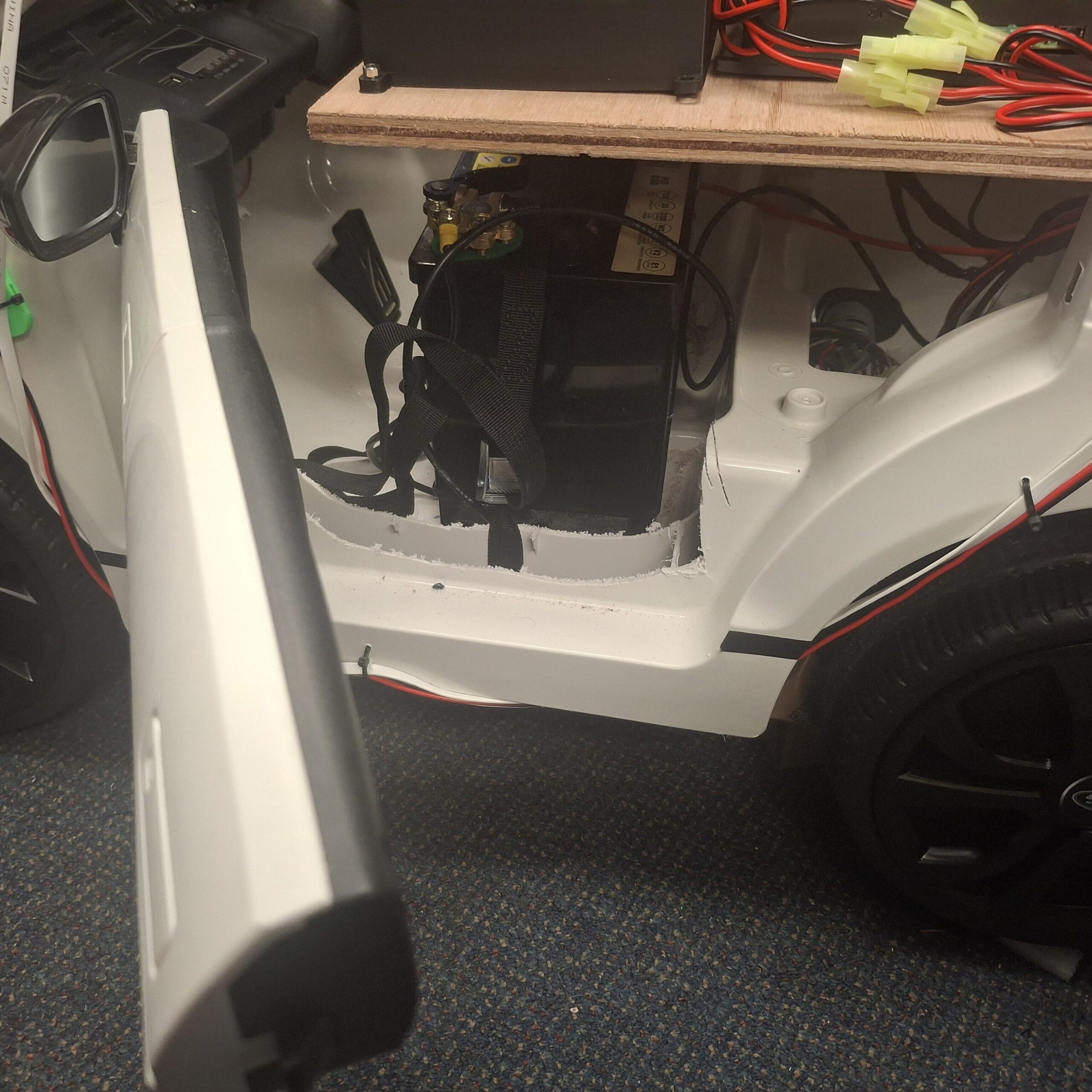
Mounting our equipment, on the other hand, took some real work. First, I knew the stock 7Ah sealed lead-acid battery wouldn’t cut it, the In-Car PC (our main compute platform) could draw up to 15A on its own, and the 12V 25W motors could draw up to another 15A to overcome rolling resistance. We estimated an average continuous draw of 10-15A, with short-term spikes up to 30A.
To keep costs down, we went with a lead-acid car battery, an old 35Ah Halfords battery we had lying around, which could comfortably handle the currents we expected. Not a long-term solution, since car batteries degrade quickly under deep-cycle use, but good enough for a prototype.
Mounting this battery was considerably harder than the stock one, it was about three times the size and weighed around 10kg. Fitting it in meant cutting away some plastic near the left-hand door, which weakened the chassis’s rigidity somewhat, causing it to flex slightly when steering.
Mounting the Electronics
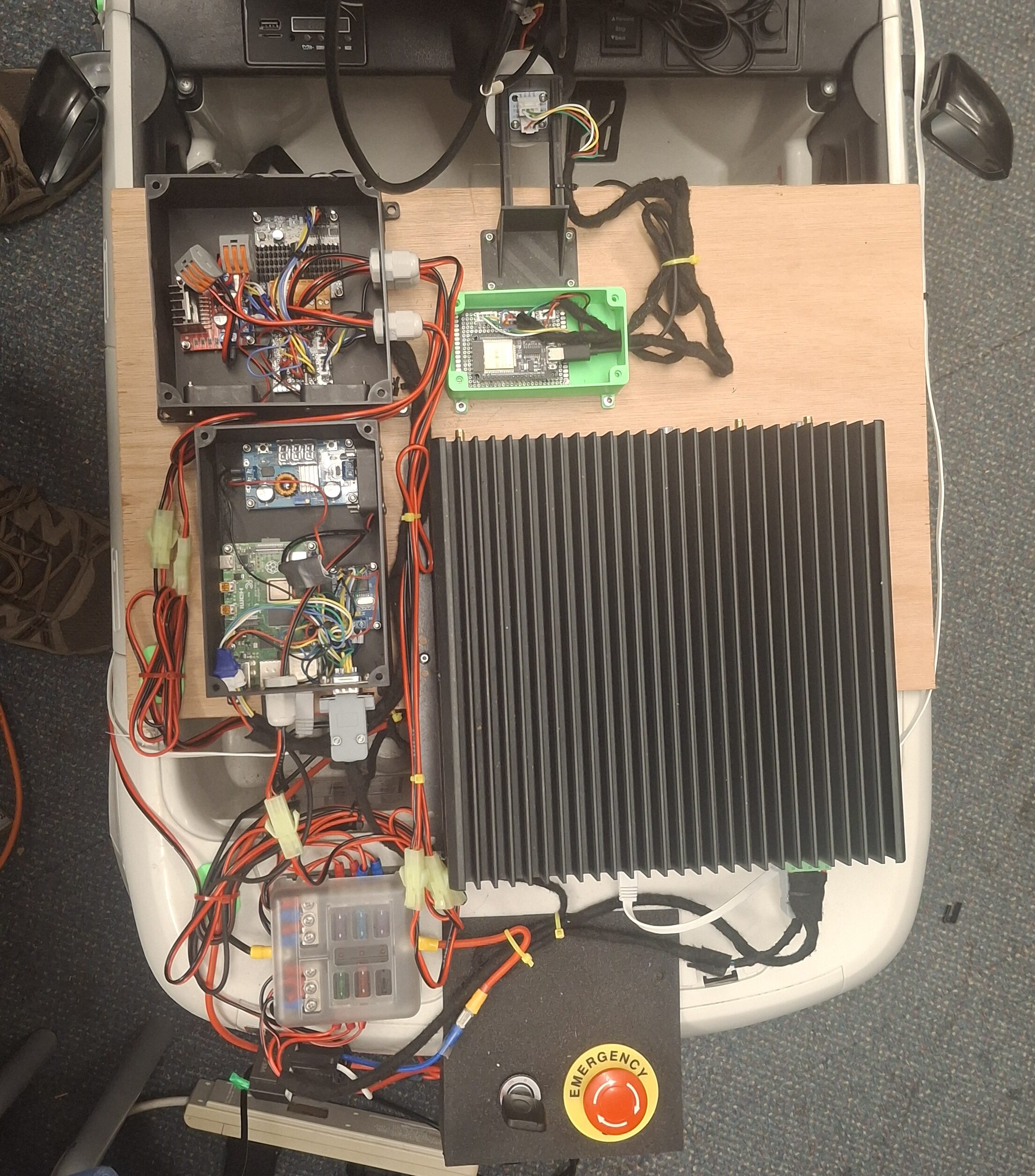
We needed to mount a fair amount of electronics on the vehicle, including the In-Car PC, Raspberry Pi, motor drivers, ESP-32, wheel-speed sensors, and steering angle sensor.
To do this, I mounted a wooden plank on top of the vehicle as a flat surface we could drill through easily and mount things to securely. It also doubled as a cover for the 12V battery and wiring underneath, offering some protection from light rain and making it harder to accidentally short the battery terminals. The plank was glued to the chassis with construction adhesive, resting on the top edge of both doors, but we left the glue off the left-hand door, so it could still open to access the wiring and let us remove the battery for charging or replacement.
Since the steering linkage was quite basic and there wasn’t much material to securely mount the steering angle sensor near the front wheels, plus the risk of anything mounted low near the front getting knocked by cones or obstacles, it made more sense to mount the steering angle sensor above the steering column, on the flat wooden plank, well out of harm’s way.
Mounting the Sensor Plate
At Formula Student, autonomous teams bring their own “Sensor Plate”, a plate mounted to the front of the shared autonomous vehicle carrying all the sensors the autonomous software needs to operate.
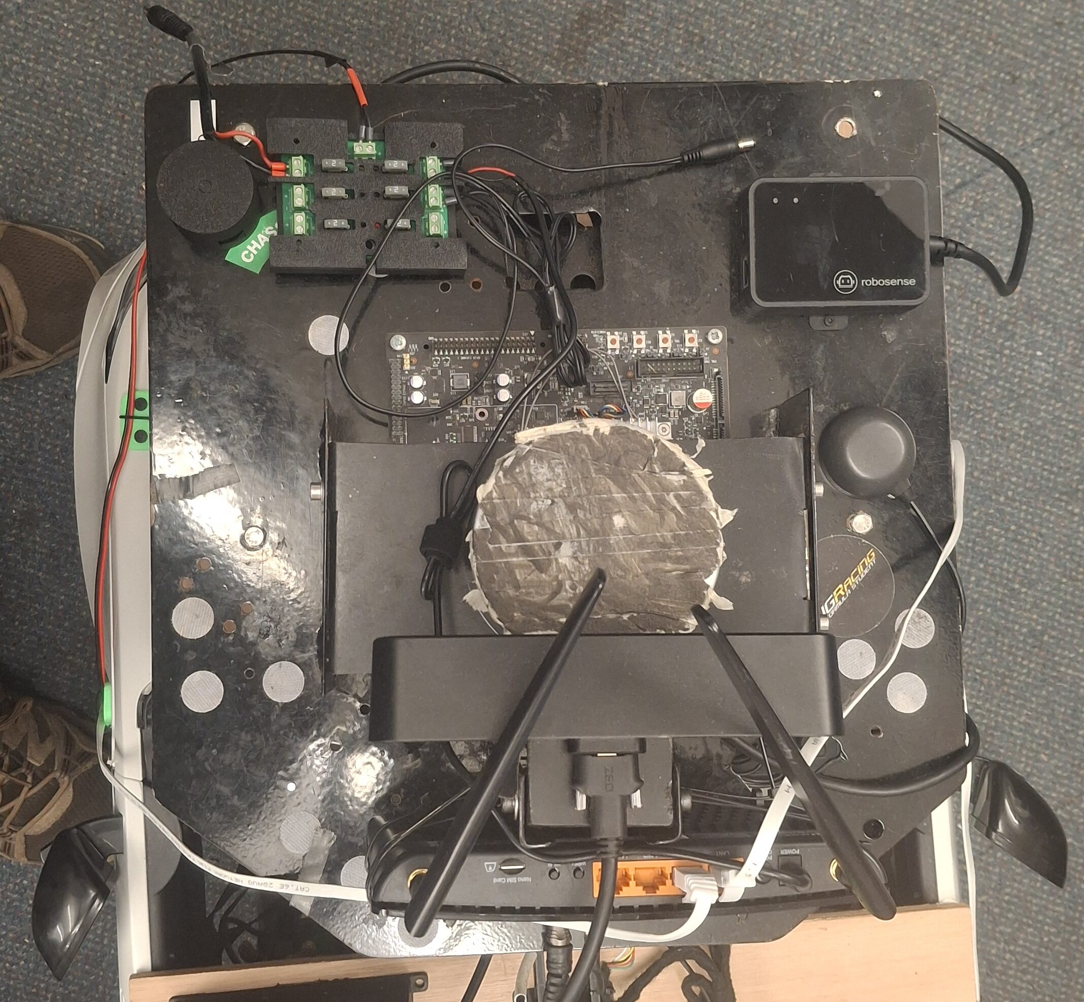
Ours holds a stereo camera, LiDAR, an IMU-GNSS module, and a WiFi router. To keep the relative spacing of all the sensors identical to what we use in competition, I designed a mounting solution on the front of the vehicle that let us fix the sensor plate the same way we would at Formula Student.
First, we fixed a wooden plank to the bonnet. Unfortunately, the bonnet sloped downward by about 5-10 degrees. Rather than correct for that, I mounted the plate parallel to the slope, giving more contact surface area for the construction glue and screws, and a more robust mount overall, so the sensor plate wasn’t at risk of coming loose while driving. Our software can be configured to account for the slight downward pitch anyway.
The sensor plate normally mounts using our threaded steel spacers, so to let those interface with the wooden plank, we drove threaded inserts into the wood, coated in epoxy, before fixing the plank to the car. That let us screw the threaded steel standoffs onto the front plate and mount the sensor plate on those standoffs with bolts, exactly as we do at competition.

Challenges
Steering Angle Sensor
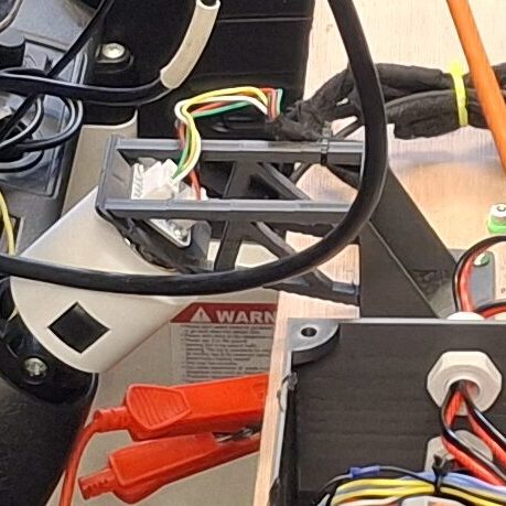
To get precise steering control, we needed to both send commands to the steering motor and read its current angle, the steering motor was a basic DC motor, so commands applied acceleration to the steering column, but didn’t give us precise control over the resulting angle.
Unfortunately, the steering linkage near the front wheels was a tough place to mount anything stable and safe from obstacles. So we put the steering angle sensor on the top-mounting plate instead, measuring the rotation of the steering column itself. In theory, that value should map cleanly to the true steering angle while staying stable and out of harm’s way.
I designed a 3D-printed bracket, starting from basic measurements and iterating by trial and error until it sat as close to the steering column as possible, then mounted it to the top plate. On the bracket, we fitted a magnetic angle sensor (AS5600); on the steering column itself, a 3D-printed collar holding a magnet.
As the column turned, the angle sensor could read the magnet’s rotation and give us precise steering control via a PID loop.
Sound in theory, but in practice, this caused some of the most time-consuming problems on the whole project.
First, I made a genuinely silly mistake: I used an axially magnetised disc magnet instead of a diametrically magnetised one. This caused inconsistent readings, but deceivingly worked fine during static testing. It was only during dynamic track testing that we realised the steering angle measurements were extremely noisy and inconsistent.
Even after swapping in a diametrically magnetised magnet, the calibration issues persisted. Several factors were weakening the magnetic field reading, making it more sensitive to external interference. Ideally, the sensor sits directly above the magnet, centred and within 1mm of it, but our mounting situation left us with more like 2-3mm of spacing and some alignment issues on top of that. Vibration and chassis flex also caused the bracket to shift slightly, and electromagnetic interference from the 12V battery (under high load) and the steering motor could distort the field being measured.
We managed to mitigate this to some extent, mainly by repositioning the battery further from the sensor and fixing it more securely so it couldn’t slide forward during operation. But steering angle measurement remains one of the platform’s biggest weaknesses, and it’s not fully solved yet.
In-Car PC Shutdowns
The In-Car PC runs our autonomous driving software, and as a PC with a dedicated GPU, it needs a lot of power. It was designed with automotive use in mind, so it has a built-in automotive-grade DC-DC converter that lets us power it straight from the 12V battery, but it can draw a lot of current depending on load, and it has a minimum input voltage of 9V.
This caused real problems: under heavy load, running the full autonomous stack while driving the motors hard, the battery voltage would sag from its nominal 12V down to 9-10V. At times, voltage at the In-Car PC’s DC-DC input dropped below 9V, and the PC would shut down mid-run.
At first, we assumed the battery just couldn’t handle the load, so we worked around it by cutting software power consumption (disabling some optional but heavy modules) and capping drive motor power. That mostly worked, but it wasn’t a real fix.
So I dug deeper. Re-reading the In-Car PC’s manual confirmed it shuts down below 9V input, but I measured the battery terminal voltage under our heaviest loads and it only sagged to about 9.5V. The PC was still shutting down, though, which meant the voltage actually reaching the In-Car PC’s input was below 9V even though the battery itself wasn’t. That pointed to a significant voltage drop across the wiring. Sure enough, swapping from 18 AWG to 10 AWG wire fixed it, we could finally run the full autonomous stack, no modules disabled, with no shutdowns.
It’s not a total fix, though, the shutdown issue creeps back once the battery has discharged significantly. Still, the system’s usable: we get about 2 hours of driving before it becomes a problem.
Motor Driver Inefficiency
The current motor controller box has one L298N module and one WSDC2412D. The first iteration, though, used three L298N modules, one per motor. The L298N is a dual-channel, BJT-based H-bridge rated for 2A continuous per channel, or close to 4A if you parallel the output channels, which is exactly what we did, one L298N per motor.
I figured that would be plenty, since the drive motors were listed as 25W. A 12V 25W motor only needs around 2A, right? Wrong. That 25W figure was likely the maximum mechanical output power, not the electrical draw, and depending on load and motor efficiency, actual current draw can be much higher. Loaded up with all our hardware and the 12V battery, accelerating from a dead stop and overcoming rolling resistance could push the motor to draw up to 10A.
Pushing the L298N modules that hard, even briefly, during starts and stops, made them overheat fast. As they overheated, their output power dropped until the vehicle simply couldn’t move itself, until the modules cooled back down.
That forced a redesign of the motor controller box around a more efficient, capable driver for the drive motors, hence the WSDC2412D, rated for 10A continuous per motor and built on MOSFET technology, which runs far cooler and more efficiently than the L298N’s ageing BJT design.
Key Takeaways
This project’s goal, from the start, was to be a prototype. It’s easy to get discouraged when you hit serious, debilitating problems that threaten the whole thing’s usability, and when the only fixes you can find, after dozens of hours of engineering, still don’t quite sit right with you. But it’s worth remembering that the point of a prototype is exploration. A successful prototype eventually becomes a usable, manufacturable product, but it goes through plenty of iteration to get there. It’s not going to be perfect on the first try, but you’ll come out the other side knowing far more than when you started, and that’s what actually counts.
It’s okay to make assumptions, just know which ones you’ve made. Assumptions are what make engineering possible; they let you take steps toward a final solution. But eventually, those assumptions get tested, thoroughly. Some will hold up close enough to work. Others will blow up into serious flaws. What matters is being able to identify which assumptions those were, figure out how to rethink them to fix the issue, and check what else those assumptions might have quietly affected.